STANTON DJC-4
SETUP
Firmware & Drivers
Install the latest ASIO drivers (for Windows only) of the unit from https://www.virtualdj.com/documents/Drivers/STANTON_DJC-4_2.9.53.zip
Drivers are not required for Mac OSX computers.
VirtualDJ Setup
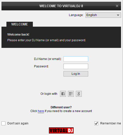
Once VirtualDJ 8 is opened, a Login Window will appear. Login with your Account credentials.
A Pro Infinity, a PLUS Controller or a Subscription License is required to use the Stanton DJC.4. Without any of the above Licenses, the controller will operate for 10 minutes each time you restart VirtualDJ 8.
http://www.virtualdj.com/buy/index.html
Click on the Use Soundcard button in order VirtualDJ to apply the pre-defined audio setup using the built-in sound card of the Stanton DJC.4 (your speakers need to be connected at the rear panel of the unit)
You can still change that from Settings->AUDIO tab.
Click to OK.
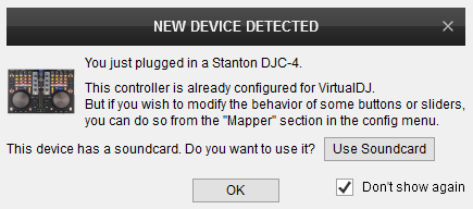
The unit is now ready to operate.
MIDI Operation
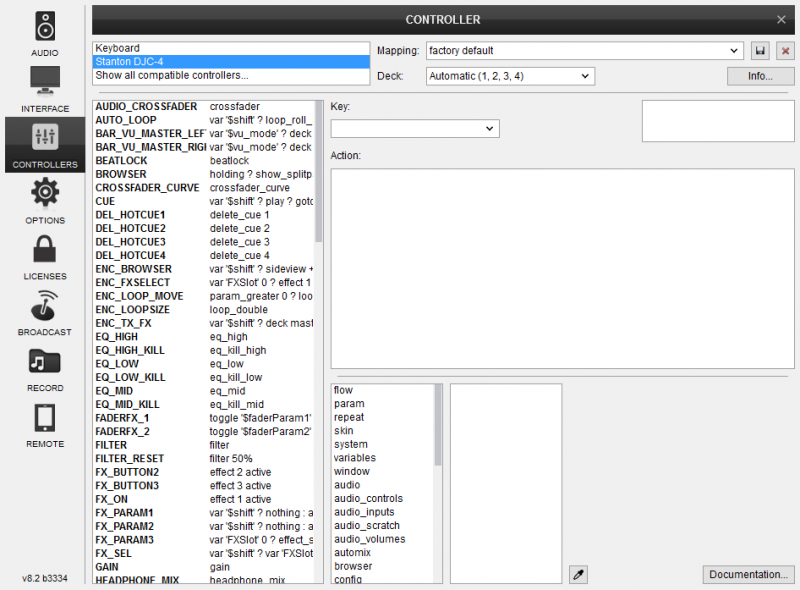
The factory default Mapping offers the functions described in this Manual, however those can be adjusted to your needs via VDJ Script actions.
Find more details at
http://www.virtualdj.com/wiki/VDJ8script.html
AUDIO Setup
Alternative Audio setups can be applied in the same window (see Advanced Setup).
For further VirtualDJ settings and features please refer to the User Guides of VirtualDJ 8.
http://www.virtualdj.com/manuals/virtualdj8/index.html
LAYOUT
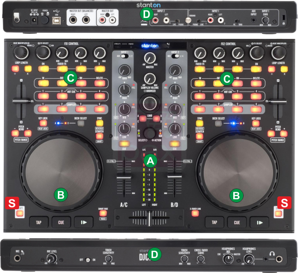
S. SHIFT. Press and hold this button to access secondary functions of other controls on the Stanton DJC4
The functionality of each button and knob per section (as shown in the image below) will be explained in detail in the next chapters
A. Mixer & Browser Controls
B. Basic Deck Controls
C. Advanced Deck Controls
D. Front & Rear Panels
MIXER & BROWSER Controls
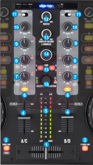
- CROSSFADER. Blends audio between the channels assigned to the left and right side of the crossfader. The channel can be assigned using the Crossfader channel assign button from the default 4 Decks skin of VirtualDJ.
Hold SHIFT down and then use this fader to control the Video Crossfader of VirtualDJ. - SMART FADE. Press this button to enable/disable the Auto Video Crossfader mode. When enabled, the video transition between left and right assigned decks will be handled automatically by VirtualDJ and the selected Video Transition.
- X-FADER LINK. Press this button to enable/disable the Link Video Crossfader mode. When enabled, the Audio Crossfader will also move Video Crossfader of VirtualDJ.
- VOLUME. Adjust the Output volume of the left and right selected deck. Note that the Volume of the decks will be controlled regardless of the INPUT switcher (11) position.
- CH/MASTER VU. By default the VU meters will show the Output Volume of the Master Output, and will show the Output Level of the corresponding deck if this is selected by the PFL/CUE buttons (6).
- CUE/PFL. Press these buttons to send this channel's pre-fader signal to the Cue Channel for monitoring. When engaged, the button will be lit.
Hold SHIFT down and then press any of the CUE/PFL buttons to toggle between the 2 different VU meters display modes as described above. - EQ LOW. Adjusts low (bass) frequencies of the corresponding channel in the software or hardware Input. Push the knob to completely cut the Low frequencies (Kill). The red led will indicate the Kill status.
Hold SHIFT down and then use this knob to adjust the Low/High Pass Filter for this deck. Hold SHIFT down and then push the knob to reset Filter to its zero (off) position (green led will be off) - EQ MID. Adjusts mid (middle) frequencies of the corresponding channel in the software or hardware Input. Push the knob to completely cut the Mid frequencies (Kill). The red led will indicate the Kill status.
Hold SHIFT down and then use this knob to adjust the key of the loaded track for this deck. Hold SHIFT down and then push the knob to reset Key to its original value (green led will be off) - EQ HIGH Adjusts high (treble) frequencies of the corresponding channel in the software or hardware Input. Push the knob to completely cut the High frequencies (Kill). The red led will indicate the Kill status.
- GAIN. Adjusts the audio level (gain) of the corresponding channel in the software or hardware Input.
- INPUT SOURCE SELECTOR. Use these switchers to determine which one of the 4 available Inputs (AUX, 2xLINEIN and Microphone) will be routed to the 2 stereo input channels of the Stanton DJC.4 built-in interface.
- MASTER LEVEL: Adjusts the Master Output Volume (Hardware operation. Movement will not be visible on the VirtualDJ GUI, nor will control the internal mixer Master Volume)
- SAMPLER VOLUME: Adjusts the Master Output Volume of the VirtualDJ Sampler
- BROWSE KNOB. Scrolls through Folders or Files. Hold SHIFT down and then use this encoder to cycle through the available Sideview windows (Automix, Sidelist, Karaoke, Sampler and Clone/Shortcuts)
BROWSE PUSH. Push the encoder to toggle focus between the Folders and the Songs List. Push and hold the encoder for more than 1 second to show/hide the Sideview Browser window.
If focus is on the Folders List, hold SHIFT down and then push the encoder to expand/collapse Subfolders.
If focus is on the Songs List, hold SHIFT down and then push the encoder to load the selected track from the Songs List to the Automix List. - LOAD. Press these buttons to load the selected track from the Browser to the left or right selected deck
Hold the same buttons down for more than 1 second, to unload the same deck
Hold SHIFT down and then use these buttons to set focus to the previous/next Browser window. - TX/FX. Use this encoder to select the Video Transition. Push the encoder to trigger the selected Video Transition. While Transition is triggered use the encoder to adjust its 1st parameter. The TX led will be lit while the video transition is activated.
Hold SHIFT down and then use this encoder to select the Master Video Effect. Push the encoder to enable/disable the selected Master Video Effect. While the Master Video Effect is enabled use the encoder to adjust its 1st parameter. The FX led will be lit if the selected Master Video Effect is enabled.
DECK CONTROLS
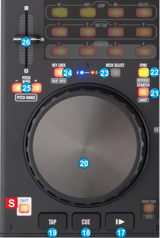
- PLAY. Plays / Pauses the track. Hold SHIFT down and then press this button to pause the track if playing or play and synchronize this deck to the Master Deck at the same time.
- CUE. When the Deck is paused, you can set a Cue Point by moving the Platter to place the Audio Pointer at the desired location and then pressing the Cue Button.
During playback, you can press the Cue Button to return the track to this Cue Point. (If you did not set a Cue Point, then it will return to the beginning of the track.).
If the Deck is paused, you can press and hold the Cue Button to play the track from the Temporary Cue Point. Releasing the Cue Button will return the track to the temporary Cue Point and pause it. To continue playback without returning to the Temporary Cue Point, press and hold the Cue Button, then press and hold the Play Button, and then release both buttons.
Hold SHIFT down and then press this button to move the track at the beginning. - TAP. Press this button to manually tap the tempo of the loaded track. Hold SHIFT down and then press this button to set this deck as Master Deck.
- JOG. Touch sensitive jogwheel. Use the jogwheel to scratch (if Vinyl mode is selected) or pitch bend. Hold SHIFT down and then use the jogwheel to fast seek through the track.
The Jogwheel also offers Loop In, Loop Out point and Loop Move adjustments (see LoopIn, LoopOut and Loop buttons) - SCRATCH. Press this button to set the Jogwheel to Vinyl (Scratch) or CD (Bend) mode. In Vinyl mode, use the outer part of the Jogwheel to bend (temporary speed up – slow down the tempo of the track).
Hold SHIFT down and then press this button to enable/disable Smart Scratch. When Smart is enabled the sound will be muted if the deck is scratched backwards. - SYNC. Press this button to synchronize and automatically match the corresponding Deck's tempo with the opposite Deck's (or the Master Deck’s if using a 4 decks Skin) tempo and phase. Hold SHIFT down and then press this button to play the track in reverse.
- DECK SELECT. Switch Left decks (1 and 3) and Right Decks (2 and 4). The left side of the Stanton DJC.4 can control VirtualDJ decks 1 or 3, and the right side can control VirtualDJ decks 2 or 4.
- KEYLOCK. Press this button to "lock" the track's pitch to its original key. The track's tempo will remain at the speed designated by the Pitch Fader.
Hold SHIFT down and then press this button to enable Beatlock on this deck. If Beatlock is enabled, the decks are kept synchronized even when moving the pitch, scratching etc. - PITCH BEND -/+. Press and hold these buttons down to temporary slowdown/speed-up the tempo of the track. When released the tempo of the track will be back to he value defined by the pitch fader.
Hold SHIFT down and then use these buttons to select the previous/next available range for the Pitch Fader ( to ±6%, ±8%, ±10%, ±12%, ±20%, ±25%, ±33%, ±50%, and ±100%). - PITCH. Adjust the track's playback speed (tempo).
The actual pitch fader will not alter the pitch of the track if the actual pitch and the software pitch value do not match (software soft-takeover, ghost fader visible on the GUI). In most cases this may happen if SYNC is prior pressed or switching decks and the other deck is having a different pitch software value.
ADVANCED DECK CONTROLS
Effects
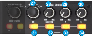 The FX CONTROL section offers control of 3 different Effect Slots. The Slot selection is made by pushing the FX SELECT (27) encoder and the Leds of the FXON (31), FX2ON (33) and FX3ON (34) buttons will indicate which Effect Slot is selected
- FX SELECT. Use this encoder to select the Effect of FX Slot 1, 2 or 3. Push the encoder to select which FX Slot of VirtualDJ you wish the whole FX Section to control.
Hold SHIFT down and then push the encoder to show/hide the FX GUI of the selected Effect. - FX 1 knob. Use this knob to control the 1st parameter of the selected Effect. If FADERFX (32) is enabled the knob will not have any function
- FX 2 knob. Use this knob to control the 2nd parameter of the selected Effect. If FADERFX (32) is enabled the knob will not have any function
- FX 3 knob. Use this knob to control the 3rd parameter of the selected Effect
- FXON button. Press this button to trigger the selected Effect of FX Slot 1. The Led of this button will blink if the effect is enabled and will be lit if the 1st Slot is selected to be handled by the top knobs
- FADERFX. Press this button to enable/disable the FADERFX mode. If the FADERFX mode is enabled (led will blink), the 1st and 2nd parameters of the selected Effect will be controlled by the Volume Faders (4).
- FX2ON button. Press this button to trigger the selected Effect of FX Slot 2. The Led of this button will blink if the effect is enabled and will be lit if the 2nd Slot is selected to be handled by the top knobs
- FX3ON button. Press this button to trigger the selected Effect of FX Slot 3. The Led of this button will blink if the effect is enabled and will be lit if the 3rd Slot is selected to be handled by the top knobs
Loops
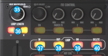
- LOOP ENC. Use this encoder to half/double the size of the loop. Push the encoder to trigger a loop of the selected size (in beats).
Hold SHIFT down and then use the encoder to move the loop forward or backwards by 10% of its size.
Hold SHIFT down and then push the encoder to toggle between the Normal and Loop Roll mode.
When Loop Roll mode is enabled, the triggered loops will apply temporary, and the track will return to the position it would have been if the loop was never triggered. - LOOP LENGTH -/+. Press these buttons to half/double the size (in beats) of the Loop.
- LOOP IN. Press this button to set a Loop In (Entry point). When a loop is enabled, hold SHIFT down and then press this button to set the Jogwheel to Loop In mode and (fine) adjust the Loop In point using the jog. The Led of the button will blink to indicate the Loop In Wheel mode. Press again to return the Jogwheel to Jog mode.
- LOOP OUT. Press this button to set a Loop Out (Exit point). When a loop is enabled, hold SHIFT down and then press this button to set the Jogwheel to Loop Out mode and (fine) adjust the Loop Out point using the jog. The Led of the button will blink to indicate the Loop Out Wheel mode. Press again to return the Jogwheel to Jog mode.
- LOOP ON. Press this button to trigger a Loop of the selected size or exit the loop if triggered. When a loop is enabled, hold SHIFT down and then press this button to set the Jogwheel to Loop Move mode and (fine) move the Loop backwards or forward using the jog. The Led of the button will blink to indicate the Loop Move Wheel mode. Press again to return the Jogwheel to Jog mode.
- LOOP DELETE. Press this button to exit the loop. Hold SHIFT down and then use this button to trigger the last triggered loop (reloop)
Hotcues & Samples
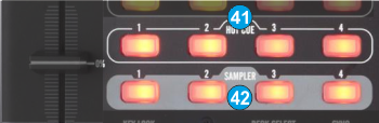
- HOTCUE (1-4). Use these 4 buttons to assign a Hot Cue Point (1 to 4) or return the track to that Hot Cue Point. When a Hot Cue Button is unlit, you can assign a Hot Cue Point by pressing it at the desired point in your track.
Once it is assigned, the Hot Cue Button will light. To return to that Hot Cue Point, simply press it.
Press and hold SHIFT and then press a Hot Cue Button to delete its assigned Hot Cue Point. - SAMPLE (1-4). Use these 4 buttons to trigger a Sample from the selected Bank of VirtualDJ. If the selected bank has less than 5 samples (slots), both sides of the Stanton DJC.4 will control the same samples. If a bank has more than 4 samples (slots), the left side of the Stanton DJC.4 will control samples 1 to 4 and the right side samples 5 to 8.
Hold SHIFT down and then press a button to stop the corresponding sample (useful if the selected Sampler Trigger mode is set to Stutter or Unmute)
FRONT & REAR PANELS
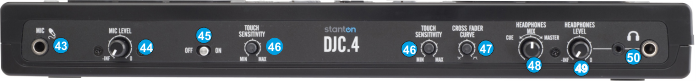
- MIC INPUT. Connect a Microphone to this Input.
- MIC LEVEL. Adjust the Volume of the Microphone Input of the Stanton DJC.4
- MIC ON. Turn On/Off the Microphone Input of the unit.
- TOUCH SENSITIVITY. Use these knobs to adjust the touch sensitivity of the left and right jogwheels.
- XFADER CURVE. Adjusts the slope of the crossfader curve. Turn the knob to the left for a smooth fade (mixing) or to the right for a sharp cut (scratching). The center position is a typical setting for club performances.
- HEADPHONES MIX: Turn to mix between Cue and Master in the Headphone channel. When all the way to the left, only channels routed to Cue will be heard. When all the way to the right, only the Master Output will be heard.
- HEADPHONES LEVEL. Adjusts the volume level of the headphone output.
- HEADPHONES SOCKET. Connect your 1/4" headphones to this output for cueing and mix monitoring.
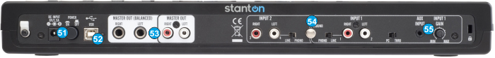
Stanton DJC4 Rear Panel - POWER: While the DJC.4 can run very comfortably with USB bus power, in cases where your computer may not supply enough USB bus power, it may be necessary to connect an additional power supply. Use a proper power 6V DC adaptor to connect Stanton DJC.4 to a power outlet.
- USB. This USB connection sends and receives audio and control information from a connected computer.
- MASTER OUTPUT (TRS/RCA): Use standard RCA or TRS cables to connect this output to a speaker or amplifier system. The level of this output is controlled by the Master knob on the top panel.
- LINE INPUTS. Connect your audio sources to these inputs and can accept both line and phono-level signals.
Use the PC/THRU switcher to send all Inputs directly to the master out (THRU) and mute the software output or to VirtualDJ (PC). See Advanced Setup - AUX. CD players, MP3 Player, Tablet Pad and other line level instruments may only be connected to this jack. Input volume will be controlled by the channel fader. The channel INPUT1 (11) selector switch must be in the "AUX".
Advanced Setup
The built-in audio interface of the Stanton DJC.4 offers 2 stereo inputs and all 4 available Inputs, (AUX, 2xLINE and Microphone Input) can be routed either directly to the Master Output or routed to VirtualDJ, depending on the back PC/THRU switcher.
External sources
Connect any CD player, Turntable or other media source to the Inputs 1/2 , 3/4 or AUX at the rear side of the unit. You can then choose one of the following ways to output those Inputs to the Master Output of the unit.
Routing Inputs to VirtualDJ
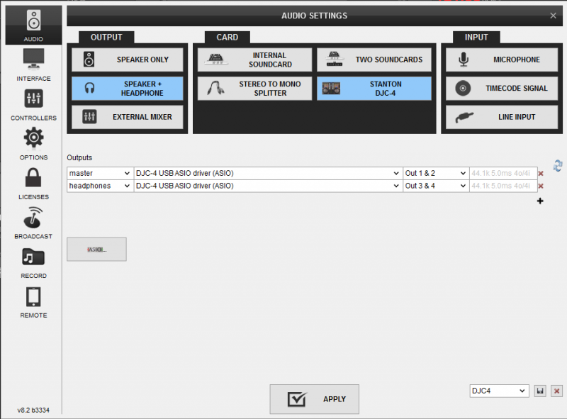
Make sure the PC/THRU switcher at the back of the unit is set to PC position. Go to the AUDIO tab of VirtualDJ config and click on the LINE INPUT button in order the following audio setup to be created.
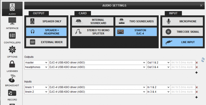
 Click to APPLY.
Once the Line Inputs are set as above in the Audio setup, 2 AUX panels will appear on the skin next to the Jogwheels (in the SCRATCH panel of the 4 Decks default skin). Click on the AUX buttons to route the external source to the left or right deck.
Use the INPUT1 and INPUT2 (11) source selectors at the top panel of the unit to select which source you wish to use (AUX/LINE12 for the left and MIC/LINE34 for the right)
Routing Inputs directly to the Master Output
This option is mainly used if you wish to directly output a media source (e.g. a CD player) without VirtualDJ to handle these inputs. Use the PC/THRU switcher at the back of the unit to route the external sources (at THRU position) or the software decks (at PC position) to the Master Output..
In this case, no special audio configuration is required (use the pre-defined that the special button offers)
Note that the mixer of the Stanton DJC.4 will not control the volume of the external sources (will not operate as a standalone mixer) except from the Master Volume knob. The mixer of the DJC.4 will still continue to control the software internal mixer, however once the THRU position is selected from the rear side, the sound output of the software decks will be muted
Timecode
The Stanton DJC.4 is capable of Timecode setup and control (DVS).
Connect your CD players or your Turntables to the Line Inputs 1/2 and 3/4. Set the PC/THRU switcher (54) to the PC position. Go to the AUDIO tab of VirtualDJ config and click on the TIMECODE SIGNAL button in order the following audio setup to be created.
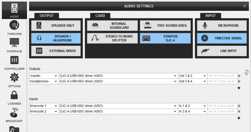
Click to APPLY.
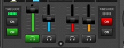 Once the Timecode Inputs are set as above in the Audio setup, the TIMECODE panels will appear at the SCRATCH center panel of the default 4 deck skin (or on the side of the Jogwheels for the 2 Decks skin).
 Use the ON buttons to enable the timecode control to any of the 4 software decks.
Note. Timecode function requires a Pro Infinity license
Microphone & Recording
The Microphone Input of the Stanton DJC.4 is directly routed to the Master Output of the unit, therefore there is no reason to modify the audio configuration in order to use it properly.
However, in case you will need to record (or broadcast) the microphone along with your mixes, you will need to choose the MIC position from the INPUT2 source selector (11) and manually create the following audio configuration by adding a mic line assigned to Input channels 3&4.
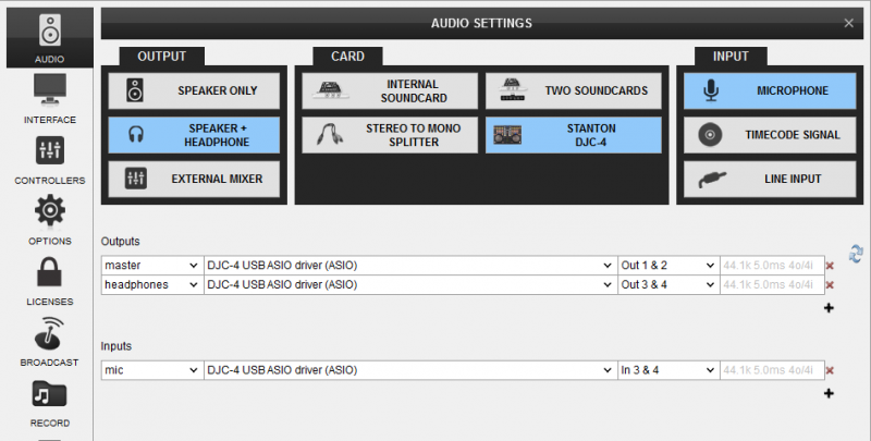
Set the PC/THRU back selector to the PC position and enable the MIC from the MASTER center panel.
Note that the Microphone will still go through to the Master Output of the Stanton DJC.4 even if the MIC ON is disabled from the software.
To operate the microphone, you will still need to adjust its volume from the front panel and turn it on/off from the front switcher as well.
No special audio configuration is required in order to simply record your mixes with the Stanton DJC.4
